The Black Dot Inspection Challenge in Plastic Tube Manufacturing
Plastic tubes used across medical, fluid handling, automotive, construction, and consumer goods sectors are primarily produced via continuous extrusion. Thermal degradation, foreign particulate contamination, and resin feed irregularities introduce dark carbonised inclusions — termed black dots or black specs — into or onto tube surfaces. These defects vary from sub-0.1 mm micro-inclusions to multi-millimetre clusters appearing anywhere on the circumference.
| Defect Cause | Origin | Consequence |
|---|---|---|
| Resin degradation / carbonisation | Excessive dwell time in die or barrel | Carbon spec embedded in tube wall |
| Foreign particulate contamination | Raw material feedstock, hoppers, ambient dust | Surface black dot / inclusion |
| Die flow stagnation zones | Geometric dead spots in extrusion die | Periodic black spec clusters |
| Screw or barrel wear | Metal micro-particles from worn hardware | Hard metallic inclusions |
| Purging residue | Incomplete purge between material changeovers | Streak or cluster of dark specs |
Why Traditional Inspection Falls Short
| Limitation | Root Cause | Consequence |
|---|---|---|
| Manual inspection fatigue | Sustained visual scan of moving tubes | Defect escape rate rises above 30% |
| Inconsistent lighting on curved surface | Specular reflection from tube curvature | False passes and false rejects |
| Sampling-based QC only | Impractical to inspect every tube | Batch contamination goes undetected |
| No circumferential coverage | Single-view camera misses back-surface dots | Partial inspection, escape risk |
| Threshold algorithm brittleness | Tube colour / material changes shift baseline | High false positive / negative rate |
| Slow response to process drift | Manual review cycle hours or days late | Scrap accumulates before corrective action |
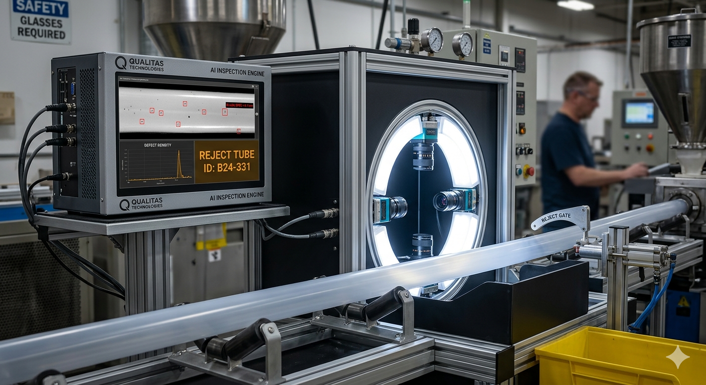
Suggested Machine Vision Architecture
Four area-scan cameras positioned at 90-degree intervals around the tube axis provide complete circumferential coverage with no blind zones. A diffuse ring LED panel provides uniform indirect illumination, eliminating specular hot-spots. An encoder coupled to the tube feed conveyor triggers all cameras simultaneously for precise spatial registration of defect coordinates along the tube length.
Images from all four cameras are processed simultaneously by an inspection IPC running a hybrid pipeline. A deep learning CNN model classifies black dot, speck cluster, scratch, pit, and gel inclusion examples. Each tube segment receives a verdict within 10 ms of image capture. Failed tubes trigger a pneumatic or servo-actuated reject gate.
| Defect Type | Detection Method | Minimum Size | Notes |
|---|---|---|---|
| Black dot (carbon inclusion) | CNN + intensity threshold | < 0.1 mm dia. | Primary target defect |
| Black speck cluster | Connected component analysis | < 0.2 mm per spec | Counted and density-scored |
| Surface scratch / abrasion | Directional gradient filter | 0.05 mm width | White lines on tube surface |
| Pit / pinhole | Morphological shape analysis | 0.15 mm dia. | Structural integrity risk |
| Contamination streak | Directional streak detector | 1 mm length | Oil or dust contamination |
| Gel / unmelted resin inclusion | Blob + halo signature analysis | 0.2 mm dia. | Translucent halo ring signature |
| Surface discolouration / yellowing | Colour / intensity anomaly | Zone-level | Heat damage indicator |
Expected Outcomes & Return on Investment
| Outcome Metric | Baseline (Manual) | With Machine Vision | Improvement |
|---|---|---|---|
| Black dot detection rate | < 60% (fatigue/speed) | > 99% | ~40 pp increase |
| False reject rate | High — subjective | < 0.5% | Near-elimination |
| Inspection coverage | Sampling / partial | 100% circumferential | Full coverage |
| Minimum detectable dot size | > 0.5 mm (visual limit) | < 0.1 mm | 5× sensitivity gain |
| Process feedback latency | Hours (periodic QC) | Real-time (< 1 min) | Rapid process correction |
| Scrap / rework reduction | Baseline | 30–60% reduction | Yield improvement |
| Payback period | — | 12–24 months typical | Positive ROI |
Implementation Considerations
A minimum of 50–100 confirmed defective tube samples covering the range of black dot sizes, densities, and positions is recommended for CNN model training. An equal quantity of defect-free samples establishes the normal surface baseline.
Phase 1 validates black dot detection sensitivity against customer-defined acceptance criteria and establishes the optimal camera-to-tube working distance and illumination geometry. Phase 2 integrates the validated system inline with the extrusion or post-extrusion handling line. Phase 3 extends to additional tube diameters, materials, or production lines.
The full application note covers detailed system architecture, camera and lighting configuration parameters, model training methodology, integration with existing MES and ERP systems, and a step-by-step deployment checklist validated across multiple production sites.